1. Introduction
1.1. Control toolkit
The LpGBT control toolkit is designed by CERN’s EP-ESE group. The tool is based on a customized Raspberry Pi 4 on which runs PiGBT control software. The Raspberry Pi playing the role of the current dongle for the GBTx, supports communication over I2C slave interface to control LpGBT.
It is meant to streamline the process of users’ familiarization with the chip and not to be used in the production environment.
Raspberry Pi is running two frameworks, a Vue.js front-end and a Python Flask back-end for PiGBT application functionality. It can be accessed through a web browser from any device, mobile phone or laptop.
No install is required. The system works out of the box. There are three different ways to access PiGBT:
- Use the wireless connection by connecting your device to the Raspberry Pi WiFi hotspot
- Connect directly a computer to the Raspberry pi through the Ethernet port
- Connect the Raspberry Pi to the local area network (LAN)
You can also connect a screen and mouse to the Raspberry Pi and use it as a standalone system without a need for phone or laptop.
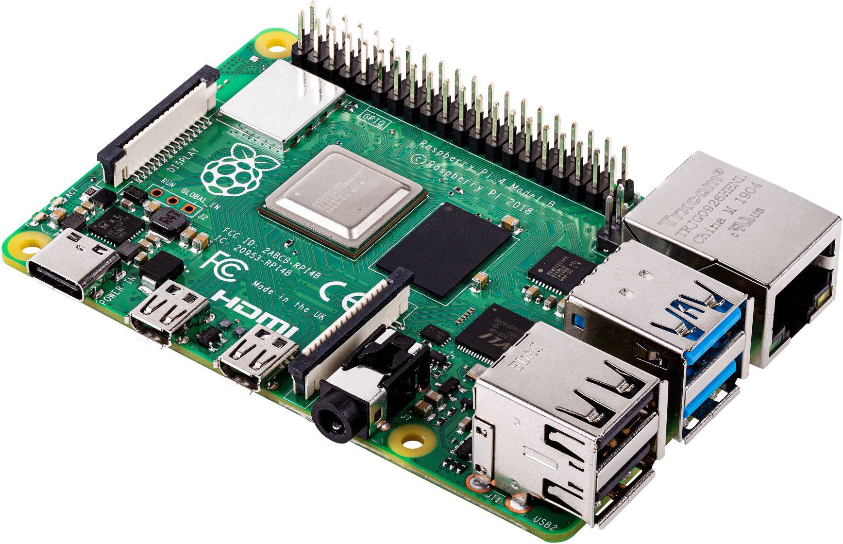
Fig. 1.1 Raspberry Pi 4
1.2. PiGBT application
Raspberry Pi is running LpGBT control software. PiGBT is a graphical interface to control and monitor any kind of LpGBT register and ease the testing and control. It communicates with the LpGBT through I2C protocol.
The application is split into two parts: a backend server responsible for communication with hardware and a frontend client responsible for user interface.
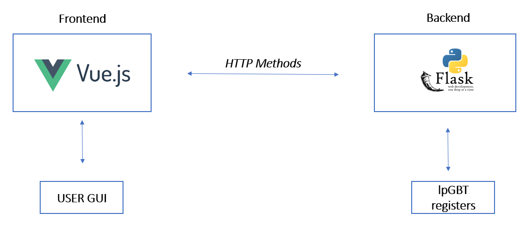
Fig. 1.2 PiGBT software architecture
The FrontEnd part is using VUE.JS framework and contains the views, meaning the web pages that communicate with the backend application using JSON.
The BackEnd part is using Python Flask framework. It contains the /api route handler and call dedicated LpGBT functions depending on the request.
1.3. User interface
To use the PiGBT application you need the Raspberry Pi translator board. This board is used, among other things, to transform the Raspberry PI 3.3 volts IO voltage to 1.2 volts to drive the LpGBT IOs. It communicates with the LpGBT through the I2C protocol. You can drive the LpGBT MODE[3:0] configuration pins, reset the LpGBT, disable and enable the FEASTMPs housed on a VLDB+ and enable the 2.5 volts to Fuse the LpGBT housed on a VLDB+.
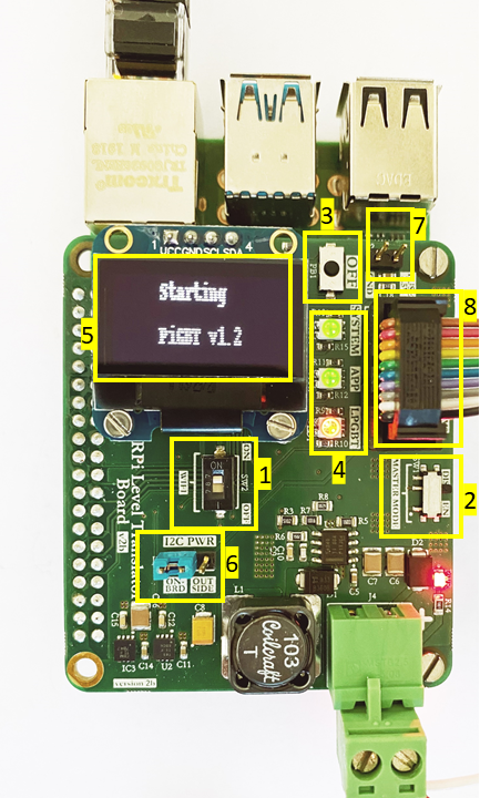
Fig. 1.3 Level translator board
Specifications:
1 - Toggle dip switches to enable or disable hot spot WIFI.
- 2 - Toggle switches to select a mode of operation for the wired connection (RJ45).
- You can choose to run the Raspberry Pi master DHCP server or client.
3 - Push-button: when pressed the system reboots.
- 4 - LEDs:
- System : this led lights up after Linux is booted (green)Sever : this led lights up after web server is up (green)LpGBT : this led is red when no LpGBT is connected to the I2C connector. It turns green when LpGBT is on ready state and orange when LpGBT is not locked.
- 5 - LCD: we display network configuration. When WiFi mode is enabled you can read the
- following pieces of information:
- WiFi SSIDWiFi passwordRaspberry Pi IP address
When the wired connection is enabled, WIFI mode should be off to read ETH IP address.
- 6 - I2C 1.2 volts power: A jumper must be put to select I2C 1.2 volts source. You can choose the
- translator board source or LpGBT external source.
- 7 - E-Fuse programming 2.5V source. This power is only to be supplied during E-Fuses
- programming. Connect the left pin of the VLDB+ W16 jumper to the 2.5 V pin (upper pin) of J2 connector using a cable.
8 - LpGBT connector: use a 10-pin cable to communicate with the LpGBT through the J13 connector.